The other night I was sitting here thinking - I've shown videos of the motor running in the donor car, and I've shown photos of the motor IN the car, but I've never gone into any detail re: what it is, or what it has had done to it. Previously I'd posted these details on a forum (http://www.boostedfalcon.net) as part of my EB falcon build discussion, so I've collected them to post here.

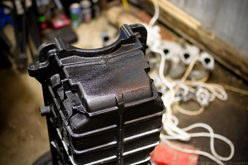
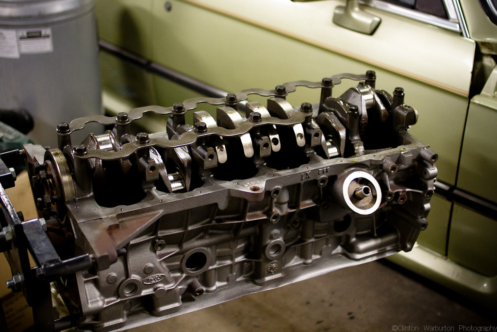
The motor started out as a $100 long motor from an AU ute. Unknown kilometers, but I bought it fully intending to strip it down for rebuild. Pictured above you can see I'd already started by removing basically everything except the distributor drive auxilary shaft and gear.
The details of the engine (when standard) are as follows:
3984CC Ford Australia "Intech" Motor
Single Overhead Cam (Alloy Head)
6 Cylinders, 2 Valves per cylinder
9.6:1 Compression Ratio
157kW @ 4,900rpm
357Nm @ 3,000rpm

The bores were a little glazed as pictured and a one had a noticable lip that you could feel with your fingernail (not so good news)

Cylinder 1 - this is the offending (lipped) cylinder.

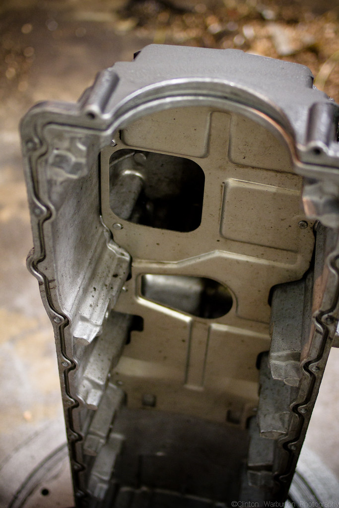
Crank and sump removed and placed aside.

No uneven wear visible on the crank (AU motors have a factory nitrided crank, so it's unwise to get it ground unless planning on re-nitriding it. Thankfully no need since it looked pretty good.

Pistons, rods, rod ends and bolts, main caps and bolts all stored in order for reinstallation.

A close up of the pistons - the plan was to clean up the pistons, replace the piston rings with new ones, and hone all of the cylinders; this in addition to replacing the big end bearings and main bearings.

Another shot of the carbon on top of some of the pistons.
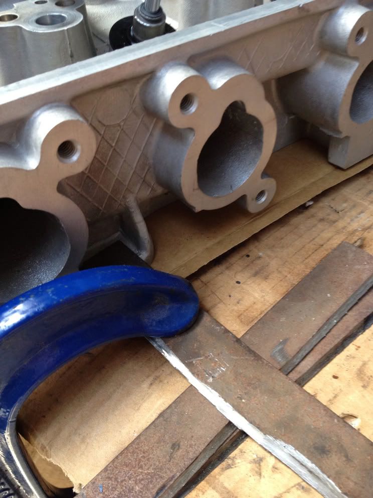
To fit in an EA-ED falcon, the front fins of the aluminium sump need to be ground down. I used a belt sander for this which made short work of it and didn't clog up like a grinder would have.
Cleaned the inside with rags, WD40, degreaser and a pressure washer.
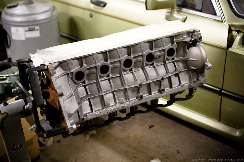
Motor back from the engine builders and partially re-assembled with all new bearings and given a quick spray with "cast iron" coloured engine enamel from VHT - you can see at the bottom the crank girdle which is a feature added in the AU motor over the EL motor - in addition, the main caps are bolted through the sump from the side forming an even stronger overall motor.
You can see there are no welch plugs installed here, new ones were installed after the paint dried.

A shot of cylinder one - early in the machining process the engine reconditioners who were doing my machining work (http://www.normmccullagh.com) called to tell me that I had two choices - the first was to re-bore all the cylinders oversize and use oversize pistons. The second (and the option I took) was to bore cylinder one only and install a sleeve, and then hone the remaining cylinders, allowing re-use of standard pistons. The reason I did this is that it means easier replacement/interchange of parts down the track if I decide to swap in a set of FPV rods and pistons from an F6 or similar (I do have a set of these in my garage)
The combustion chambers and valves got a very rough clean up but ultimately the head needed to go to the reconditioners for a skim and for the valves and valve seats to be re-cut.
Another shot of the crank girdle/crank all installed.

Here's a tool I made to make the process of compressing the valve springs much faster. This involves (for anyone with one of these motors) removing all but the two end pedestals and all the rocker arms from a standard set of rocker gear, then sliding this onto the arm; more below:

Basically you push down on the lever to release the tension on the spring, pull the collets with the magnet and hey presto, spring released.

Voila!

This process makes short work of removing the springs.

Then you can just turn the whole assembly around by 180 degrees.

Crow Cams VTK-AU-R double valve springs

Here you can see I've removed some of the valves. I believe initially I was going to try and just grind the valves using grinding paste, before I realised I needed to machine the step off the valve seat to suit the Crow Race springs and that it would have to go back to the machinists.

Here I've removed the swirl pot and deshrouded the valves. This helps flow and reduces sharp areas in the cylinder likely to cause hot spots and detonation. Basically copied from photos posted on www.fordmods.com of a Jim Mock Motorsports head job.

Close up

More de-shrouding

More de-shrouding. All of this was done with a carbide bit on an air powered die grinder.

Test run - all the crow springs installed - this is without the seats machined, using the stock shims. I realised once this was done that the inner of the two springs in the double spring configuration would bind at the level of cam lift I wanted to acheive and also that the thinner standard shim would mean the installed height of the springs would not be correct and the results would be different spring pressures than intended.
Here's a video of the spring compressor in action - so you can see just how quick the process is with this tool.

Here's how I kept the head from flipping over while doing the springs - clamped to the desk.

Close up of spring installed on standard shim

The lip that has to be machined flat (note the valve stem seal is still installed in this image

Showing the double spring assembly

This is the crow shim, placed here purely for illustration purposes, see the factory step below that has to be removed, and also note the overall thickness of this shim compared to the standard shim.

Head back from machining - note the spring seats are now flat.

Another shot. Obviously new valve stem seals were installed as part of this process.

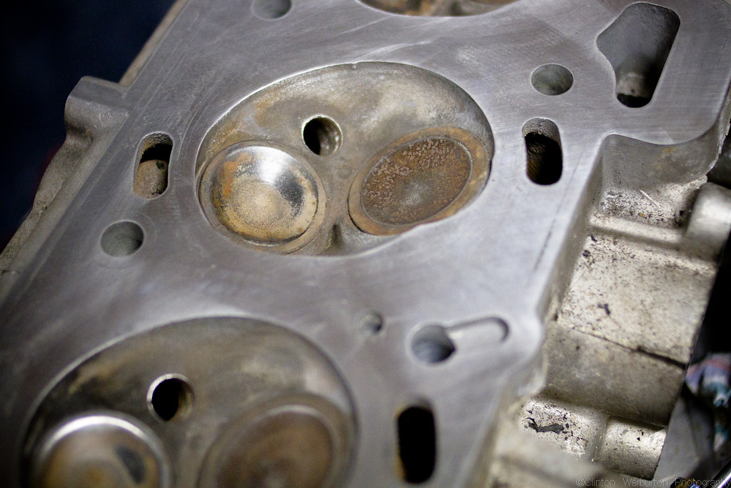
Planed head, note new 3-way valve cuts and combusion chamber cleaned up with a cartridge wheel by the reconditioners.

Close up of the valve seats and combustion chamber surface. Note, ideally you don't want this too smooth as otherwise combustion gasses, carbon, oil and fuel can stick to the cylinder head too easily.


Cam timing done, motor installed in the car and Reground Camshaft installed.

These Nason lifters were installed as the initial set I tried to use (cheaper alternatives also from Nason but without the seating o-ring) had failed dramatically - to the tune of 80% of them being broken. I believe this is due to running two shims with reground cam in my past motor, so in this motor I took a different approach. I don't have any photos because we're only talking minute differences, but I had the machinists take .015" from the rocker pedestals (an idea they weren't too keen on, given the difficulty involved with getting the setup flat in the mill) and also had them leave the valve lengths after re-cutting the valve seats and re-grinding the valves. This in itself gained .030" in valve height. The .015" taken off the pedestal is at the pivot point for the rocker arm so equates very close to .050" at the lifter; acheiving the same overall tolerance change as adding an extra factory shim (0.079" or 2mm).
This also happily improved the lifter->valve angles back to near-factory, unlike the normal effect when running two shims.
This and the valve springs were done to accommodate the coup d'état of this whole project; the Wade 992-AU cam regrind. Wade list the biggest "normal" regrind for an SOHC on their website as the following:
Profile name: 1521a
Duration: 217 degrees
Exhaust valve lift: .524"
Intake valve lift: .524"
LSA 114
Use: Mid to top end, manual or high stall, requires better springs and modified ECU
I had two mates who got the 1521a reground with a tighter LSA after I discussed with them that I was planning the same, so I called and asked for something bigger (hey, you've got to get an advantage somewhere!)
I got the 992 profile ground onto the original AU camshaft:
Duration @ .050": 222
Exh valve lift: .531"
Intake valve lift: .531"
LSA 110
Anyway I'm sure I've already posted it up here about three times, but here's a video from when we first got it running with the cam and new lifters:
And here's what it sounds like in action (sliding on dirt in the EB) - I should mention that this is with the rev limit set to 6,250rpm (standard is 5,500 for non-tickford motors and 5,700 for tickford)
I can't wait for this to be running in the E21!
No comments:
Post a Comment