I've been doing some thinking lately in regards to the fuel system, and as luck would have it, I found a buyer for the standard Getrag Manual from the car.
As a result, this has allowed some "self-funding" for some desperately needed parts for the car. Today I placed an order for a 40L Aluminium Fuel Cell from At Racing World via eBay:
I'm also in the process of trying to work out what Fuel Pump to buy to support the 4 Bar regulator. I know a lot of the Bosch 044 pumps on eBay are of questionable origin, as are the Walbro ones, so this process could take some time.
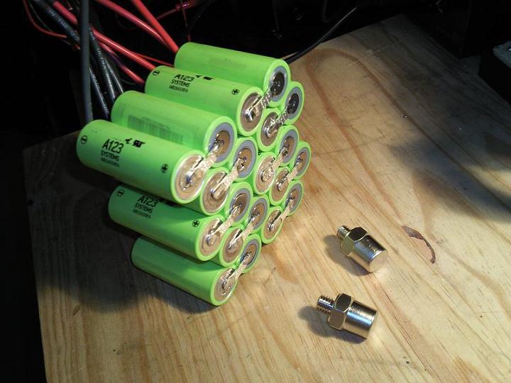
Basically it outlines a battery made from Lithium Ion cells that is 400CA, 11Ah and only 3.5 pounds (1.6KG) which means it's small, convenient, and better suited to sitting in an un-used car as it will lose less power when sitting disconnected than a traditional battery would. It also means there is no requirement for ventilation, so I'm thinking something like this might be the go for the car too.
Ever since I moved house a few months back, I haven't been able to weld in the front garage (where the car is) because the garage powerpoints share a circuit with the kitchen, laundry and study. These three rooms already struggle with power, tripping a 15A breaker so many times I've had to resort to installing a 20A breaker on that circuit, and I didn't want to risk losing data from my PC or NAS, or damaging my fridge etc by welding on that circuit.
So, I've finally had a dedicated 15A welding circuit all hooked up and it's ready to go! Now I just have to get my welder back from my old man (who is using it to weld replacement panel patches onto his 1974 Chevy Camaro project) and I can tack this brace together and test-fit it!
Dragged the chop saw out and quickly cut up another length to make manuevering it around the front shed a bit easier - the setup in this back shed is getting closer to how I want it but it's still a bit of a chinese picture puzzle moving things around when I need to use the space. There are a few items yet to find a new permanent home.
Chopped to near the desired size, ready to go.
Tonight I got sick of not being able to see. I've picked up four fluro light fittings which I have to repair and can then mount to properly alleviate the issue, however in the meantime I've replaced one of the compact fluro globes with a 200w 240V incandescent globe (see if you can guess which one from the photo above)
As a result, I can see somewhat better now - although the main issue with these lights as they sit is their location causes nasty shadows unless you're working with your back to a wall, and is useless almost anywhere if you have to work on the side of something. Here I've cut out yet another section of the radiator support.
And another. I'm noticing as I go that my drawing isn't quite sized accurately and as a result some of the angles are resulting in larger than ideal gaps. This will make the welding interesting. I may have to re-do some of the pieces to save a bit of time and frustration in the welding process.
Here's another piece added to the mix
This long bar will run across just above the belts on the engine. I am hoping it clears the top radiator hose. If not, I'll have to cut it and build a new section that goes up and over once the rest is done.
Here I've cut the far end and matched it all up to make sure I'm keeping my overall width correct. All looking good so far!
Essential safety gear - protective footwear not required!
Just a reminder of the abomination I'm replacing with this new assembly
The first of the front pieces done - note that the original (see line to the left of this bar) radiator support has a slight curve - I will be welding on some spacers for the headlight surround mounts once the rest is complete.
And the other side, here the curve is still present although the angle of the photo doesn't really show it.
Front piece done - once this is welded together a couple of tabs will have to be added to this piece as it's actually higher than the rest (for the grille mounts)
Can't wait to get it tacked together so I can sit it over the car to check it's all O.K.
So tonight I decided if nothing else I'd measure out and draw up the essential dimensions of the radiator support.
That was easy enough. What do you know, now I have an empty bench top with a sander and grinder, and my angle grinder is in the front shed. Off for a short trip to get an offcut of 25x25x2mm galvanised RHS from the back shed.
A closer shot of the driver's side - this is shown from "underneath" due to the way I used the light plastics as a template for the front edge. Note the cross frame - this is for strength - the reason the member at the top comes in sharply is that it has to go around the coolant reservoir. You should also be able to make out where it's marked "booster" - this is where the factory booster bracket mounts and is at the same angle as the original. I am not sure how it will compare in terms of height however if required I will just weld a sleeve to the support for the bolt to hold the brake booster. Note the radiator sits level with the booster as well so I can't just have a member straight back from the booster to the "front"
Passenger side - crossed out line follows factory piece dimensions, however cross brace needs to run between engine and radiator so I have adjusted to suit.
The sander and grinder were both being stored on this bench. That's handy!
Piece "A" cut and placed on the template. This is pretty quick going. If only I had my welder handy to tack these in place.
Piece B - seems to be lining up pretty well so far.
Piece C - a bit of a hiccup in the top corner with a larger than intended gap. It's ok, I can bridge that with weld easy enough.
These corner joints look to be the bomb.
Another couple of pieces before I ran out of offcut steel. I'll have to grab another length from down the back tomorrow to continue.
So today I pulled the front bumper and BBS plastic over-spoiler off the car so I could have a better look at locating the fan. I got my hands on a commodore A/C fan however the critical dimensions on these fans are the same as those on the falcon fan - the blade pitch and weight of the motor are not as impressive however so despite the virtue of their "ease of attachment" - being that they are designed to bolt through the radiator - I will be opting to use the falcon unit anyway.
I also fitted up the radiator supply hose. The hose I've used is originally intended for an XH ute and only needed approx 2" removed from each end - perfect! Note however that I'm constantly running into clearance issues with the dual headlight front!
This section just below the bracket that the bottom of the headlight buckets locate against needs clearancing as the radiator (with front bumper mounted to car) sits hard back against this spot normally.
The headlight bucket also needs modification; here I've marked the approximate problem area with a chalk marker. Note the rather agricultural tin snip attack to the left of image which resulted when trying to remove the radiator with the front bumper fitted to the car.
And here it is suitably modified. A quick test fit shows it should now clear ok. Note that the bracket is in the vice "upside-down" so the area I've actually reduced is the bottom. The strange part is how over-engineered these brackets are! Despite the huge amount removed, they do not flex at all by hand!
I've got a dilemma when it comes to the remainder of the radiator support panel - more on that later - here you can see I've cut the panel for clearance on the top bleed hose from the radiator to reservoir - this will at least work to get this going temporarily.
You can also see a shot where I've clearanced the bottom bracket.
Here's the top bleed hose located to test the clearance. This means I only need to get a T piece, run the bleed hose from the thermostat housing, and work out the most difficult of all the hoses - the bottom hose.
I've undergone a bit of a rethink at this point however - I'm not happy with the current radiator support as it doesn't provide enough support for the brake booster, and with the light supports removed the whole assembly flexes far too much. Add to this that the fan will be mounted with very little "wiggle room" and you have a recipe for disaster.
I think the best plan at this point is to remove the whole radiator support including the existing end sections I've retained, and to fabricate a frame that runs across the front, picking up the mounts for the headlight assembly per the factory support, as well as running behind the radiator (above the engine belt assembly) and integrating the radiator mount points also, allowing the whole unit to be removed easier, to better support the brakes and headlights, and to better support the entire front end assembly.
So tonight I started to sort out the cooling system. From the factory, the E21 radiator overflow bottle (pictured bottom left) is located adjacent to the strut tower, above the exhaust manifold.
The exhaust manifold did not in itself present any issues as I have heaps of clearance in terms of height back there however the normal hose path goes to the radiator which is accessible from the inner side of the brake assembly. In my case (as you will see in photos further down the page if you are new to the build) the radiator supply hose has to be accessed from the outer side of the brake booster so I cannot use the standard location.
In a standard application of "measure twice, cut once" I made sure there was enough clearance for the bonnet using the unscientific "put it in there and close it" method; then made a bracket to hold the supply bottle. I had to remove the rear mount as it did not allow the bottle to sit flat. I may JB weld a new bracket to the bottle if it moves too much once filled. The bracket was made from 40x40 angle aluminium
The new location means a relatively simple path for the hoses, and also means the reservoir is located higher than the rest of the system and still "flat" as per its original location - this is vital to ensure the system can self-bleed. Note that the standard falcon item doesn't appear to be an easy fit in this location; thankfully the BMW unit seems intact and uses the same size hoses. The only thing missing is a second bleed hose nipple, however I will just fit a T piece to work around this.
Here you can see the main bleed hose nipples - both on the reservoir and the radiator - I will have to drill two holes to allow the hose for this bleed to pass through. I will most likely fit the T peice at the top of the system right next to the reservoir and feed the other bleed hose along the top of the radiator and along the path you can currently see the headlight wiring following.
Side profile showing bonnet pin location and reservoir/coolant cap - here you can see how far proud the setup sits.
With the bonnet fitted, inside you can see clearance is very tight - less than 1cm on both the cap and the un-tapped bulge at the front of the reservoir (This bulge appears to be intended for a sensor perhaps?)
A wider shot showing the hose outlet, you can also see level with the top of the bumper the hose outlet from the radiator. Some major cutting will be required both in the area around the bottom headlight and surround mount, as well as most likely the headlight bucket itself to clear the hose. Sometimes I think it would be much easier to simply opt for a single headlamp front. Despite feelings of the opposite from some E21 fans, I feel the twin light front "makes" the car, so will continue to work to preserve that look.
A shot showing the bonnet pin so you can see roughly where the bonnet sits in comparison to the reservoir. It's close!
I can't fire up the compressor to use the die grinder to modify the headlight brackets tonight so instead I've moved on to looking at making a thermofan fit. I have no room for a clutch fan (and there is no provision for one anyway on the EF-AU belt setup) so have to make a thermofan fit. I have removed the brackets from an EF-AU fan (single unit) - normally these are configured with dual speeds and have two fans (one comes on with A/C) - since I don't have A/C I shall only need one fan however I am going to struggle to get it to fit - hence removing all plastics/guards etc.
Here's the back of the fan - you can see there are three locating bolts - if I can make a bracket that holds this and modify the top center of the metal front bumper (and possibly the plastic grille/headlight surrounds/their mounting locations) then I should be able to make do with this fan. The alternative is an A/C assist thermofan from a Holden Commodore - these appear thinner however one can only assume that their flow capacity is also reduced. I will look into this further before hacking into the bumper as I do have a commodore unit available to me.
The overall airflow may not matter massively as the thermofan will most likely only be needed while idling or cooling down after driving (when the engine is no longer under load) - I have no intention of performing stand-still burnouts (where a clutch fan is traditionally far more advantageous)
The core is around 3" thick (apologies for the mix & match of metric and imperial sizes - I find it far easier to be precise in mm, and approximate in inches!)
Measurement is 1.5-2" from the bracket/base to the fins
The core would clear at the very center, but will require clearancing either side - this may impact how the headlight bracket sits. One of the main reasons I'm considering the commodore unit.
At the outside edge (both sides here are symmetrical) - the headlight bracket to the left would have to be trimmed (see black line) and clearanced slightly.
I've also sorted out a top hose - this is taken from a commodore (I believe VQ V8) although V6's have the same 90 degree bend that lends itself to our requirements. You can also see the Blue Bosch injectors from a BA per my last update, and the ford Belt cover. Note also minimal clearance this side of the radiator - there's certainly no "moving it back a touch" to gain clearance at the front.
A closer shot.
The video above shows how I install and remove the bonnet on my own - this certainly helps when trying to get small pockets of progress achieved late at night on my own!
Anyway, I still have to grind out the clearance I need for the side hose, and the bottom hose may require an adaptor and a cut-n-shut from an existing hose as it's a couple of compound bends from one to the next. I'll also be looking into the commodore fan further to assess it's flow capabilities. If nothing else it might prove sufficient to allow the car to run/idle and check timing etc.


.jpg)
.jpg)
.jpg)
.jpg)
.jpg)
.jpg)
.jpg)
.jpg)
.jpg)
.jpg)
.jpg)
.jpg)
.jpg)
.jpg)
.jpg)
.jpg)
.jpg)
.jpg)
.jpg)
.jpg)
.jpg)
.jpg)
.jpg)
.jpg)


