Wednesday, January 30, 2013

Some adjustments

So tonight I decided (around 10.30PM) to go out and have a look at what still needed to be fitted up on the car. First and foremost I needed to confirm for myself that the power steering pump will now fit; which it does (hooray!) 


Unfortunately, the very next thing I noticed while trying to work out how best to run the power steering lines, is that the sump was sitting on the power steering rack lines. The AU sump is a completely different design to an early sump and has aluminum braces instead of being a thin, steel sump. I carefully clearanced part of one of these fins with a carbide bit on my die grinder (very finnicky with the whole lot in the bay!) then spaced out the engine mount on this side to allow clearance over the banjo bolt beneath the line (which it sat down on as soon as I clearanced the rack line)


I soon decided my existing attempt at a gearbox mount was failing on two fronts; first it was not holding the gearbox assembly anywhere near high enough for my liking, and secondly - it looked as weak as a chinese carnival toy. I removed the vibration dampener bolts - I am going to put some 25x50 RHS through the trans tunnel on either side here and then will connect longer bolts through the dampener - this will retain the smoothness of a traditional style rubber mount but allow a much higher, firmer mount without interference with the tailshaft.


Hole partially cut; then I called it a night as it's midnight; and I'm sure my long-suffering neighbours already hate me enough without me grinding into the wee hours of the morning.


Monday, January 28, 2013

A milestone has been reached!

So, today Michael "Hamo" Hamilton and myself set out to acheive a simple goal - to remove the temporary motor from the E21 and to finish welding the firewall. I must say we progressed far further than I expected in the timeframe! Read on for more:

First we began by removing the radiator and radiator support. The front of the E21 has to be lifted by the k-frame with a trolley jack otherwise the engine crane does not fit under the lower control arms; this has been the case even prior to lowering the car, so no changes there! Undid the tailshaft and centre bearing and removed the tailshaft, undid the gearbox mount and engine mounts and out came the engine.

It barely put up a fight, only getting stuck for a brief time on the steering rack.

Hamo took a while to get into the swing of things, preferring instead to take up his traditional position as supervisor. Progress was slow until he kicked into gear!

Here's a shot of my rather nasty hole chasing welds along the top of the firewall; They aren't pretty but they serve their purpose! I have some proper resedagruen paint, however I prefer to retain that for the exterior of the car, and am just using paint I have lying around the shed to cover up welds, hence the "aged bronze" rustoleum coating seen here:

Our preferred method of moving these cars around the yard is the trusty mower - Since summer has all but killed the lawn (notice the colour) - there isn't much other use for it at present!

Turned the EB around with more help from the mower; I've a very amusing video to cut together to show this in action! Pushed it into the shed and put the bonnet in the "engine removal" position - for those of you that don't know about this, you remove the struts from their normal mounting position and then push them into the holes which are slightly below and inboard of the standard mounts; you should be able to get the gist from the image below:

Hamo decided to get stuck in; and we made short work of the wiring looms, grounds, engine and gearbox mounts, shifter, fans, radiator and all the other parts which require removal prior to pulling an engine. It helps that we've each done this in excess of 10 times.

I really need to invest in a load adjuster for my engine crane. Getting to this point and having to man-handle the gearbox is really not worth it!

When that proved too hard, we used a combination of brute force and a ratchet tie down to lift the back of the gearbox, before finally lifting it the last few inches clear of the radiator support.

Finally, it was out! Note I knocked the CV out of a tailshaft yoke and installed in the rear of the gearbox to retain the fluid, which has probably only done about 10,000-15,000km of service.

It started to rain, right when Hamo began to change the distributor (I believe the hall effect sensor is the reason my EB was suffering from a progressively worsening intermittent ignition issue) so I grabbed some builders plastic and created an invention that I shall now refer to as the Outdoor Engine Maintenance Clean-Room or OEM-CR

From this point, now oblivious to the rain, Hamo proceeded to change the distributor and engine mounts ready for installation into the E21. This is the point where things get "interesting"; he discovered that a couple of the bosses used on E-series motors are not drilled or tapped on an AU motor (which this is) - as a result only two of the locations I had set up for one of the mounts could be used. The other has three. I don't think it's that big of an issue to be honest; when removing the old ones - one was only held in by a single bolt! Seems I've been leaving a trail of engine mount bolts behind me on the odd occasion as I certainly installed them all with the motor!

 We set-up a heater bypass; yes we did use hose-clamps - this is just to make sure the curve and lengths are correct.


While Hamo was busy in the OEM-CR, I cleaned up and quickly sprayed the K-Frame, steering rack and chassis rails.

Installing the motor; had to slide it over a block of wood to prevent the steering piping from being caught and bent; and had to remove the belt and power steering pump after this shot as the pump was fouling on the brake booster; however now the engine is sitting in it's correct location, the power steering pump should clear with a small amount of wiggle room.

The bigger issue that we ran into is the sump. The AU sump is MUCH larger than an e-series sump, in my EB I had to modify the K-Frame for it to fit comfortably; there's no such luxury in the E21. I'd only had what I shall refer to with the very technical term of "a bee's dick" of clearance between an e-series sump and the swaybar in the E21. I'd always wanted to remove the front swaybar; however the logistics are a bit of a nightmare as it also serves as the castor rod or front control arm in this setup; Since I now have NO option, I had to cut the swaybar to clear the sump. I'll be looking into making some new control arms and possibly adapting an E-series rear sway-bar for use on this car now. I didn't have the right size cutting wheel for my grinder so I very carefully used one that was much too big (pictured)

See, the engine fits, as long as the sway-bar doesn't need to be there as well.

Finally in place in the bay! Now I only need to reinstall.... everything. Build an exhaust, etc. Still a lot of work to go yet, but it feels like we achieved a hell of a lot today; and it's good to finally have a capable engine in the car just WAITING to be fired into life!

I leave you with this image, and the promise that there's more to come!


Edit: here's the video compilation of some short clips showing how we move things around the yard with the help of a ride-on lawn mower.

Over the pit and ready for it!

Just finished tidying up the garage, so I can spend tomorrow removing the temporary engine and box, and welding up remainder of firewall. After that, it's time to transplant the heart from my Eb!

Monday, January 21, 2013

Nothing is happening

Since the shed has been in use for other projects (namely polishing and other touch ups to the E39 and R33) I haven't got any work done on the E21 lately. I should be able to get it into the shed some time next week to remove the temporary motor and gearbox that are currently installed, so I can finish welding the firewall and start to get ready for installation of the "real" motor. In the meantime, I've been playing around with some "paint" ideas for the car for fun;


Scarlett approves, since I put the tape on it she now refers to it as a race car every time she sees it!


Another idea floating around my head is stencilling and then painting the ADAC eagle full height on the doors as per the picture below, then rubbing it as it dries to get a distressed/aged look. Maybe this in combination with the military crosses?


Sunday, December 16, 2012

Cut springs and other things

So I spent most of Saturday on another project; helping clad my daughters Christmas present; a "Cubby House" - the reason it's in quotation marks is that it's rather well built - silverwrapped, will have pink bats, and it's on a movable steel skid that is designed to fit into our trailer when we move (we're currently renting). It's a bit of forward planning so as she gets older, instead of falling into dis-use, it will become her own "space" for study etc.


Next up, a photo from work I did a week ago but forgot to take and upload - the mounting bracket and location for the Ford EEC-IV ECU:


Next, here's what I decided to do this weekend. I have problems staying motivated on one task at a time (if you've been reading this build the whole way, that may have become somewhat obvious to you in the way I chop and change between different aspects of the build!). I decided to cut the springs for more low. The shocks on the car seem really good (no extra bounce etc) but when I drove it last (i.e. when it was still registered, but with overheating issues from the engine limiting drive-time) it had far too much body roll for my liking.


Before


Much to the chagrin of the E21 evangelists on Bimmerforums (see discussion thread here), I decided to cut the springs as an initial step. I don't intend on returning it to standard height with factory springs (if I need it higher for Rally down the track, I will do it with coilovers with stiffer springs to control the body roll!) so am not losing anything by cutting the originals. Plans down the track (for adjustability and added stiffness) is to get a second hand set of S13 or R33 coilovers to make fit and work on this car. In the meantime, the fronts are Bilstein and the rears Koni Yellows, so the shocks should still do okay for a while.


I haven't taken an after version of this shot yet as I'm waiting for the springs to full settle overnight; however this is a "Before" shot of the driver's side rear standard height.


I went with a two coil cut, as recommended by one of the few people on BF not abhorred by the sacrilege I was about to bestow on this poor 3 series (let's remember, I tried selling this car intact before I began this project but got zero interest - if it wasn't for this project it would have been scrap metal a long time ago!).


I used an air powered grinder at first. Unfortunately, this one is cheap and fairly hungry for air. My grandfather bought it at Aldi then decided he didn't really need it. I'm glad, as it's the only "straight" grinder I have, and despite having to stop many times and wait for the air compressor to "re-charge" so I could do the job, it was a much better tool for the task than my normally trusty angle grinder due to doing the cutting in the car. Here's a bit of info for anyone looking at lowering an E21 this way: with the rear of the car off the ground, the rear springs aren't really under any compression. There's enough to stay captive, but not enough to break your grinder/arms/face when you cut through. If you're unsure, try and compress the springs slightly with your hand - if you can get a bit of wiggle out of them then it's probably OK.


Enlisting the ever present help of Mr Hamilton, yet again. Cutting the spring becomes a two step process, as we're taking off two coils, it's not possible to remove the cut off section easily without cutting it in half again; it's easier to cut two, then in half than to cut one at a time, as the first is very close to the spring perch (and you don't want to be cutting that!) - see below:


Here it is with both rears done, and lowered back down - note it hasn't fully settled yet. I'm not expecting any massive changes as the springs have already put in years of work, however the change in the amount of spring/leverage to the weight of the vehicle may mean they have some slight give in a day or two - we'll see what happens!


In the front, you MUST cut full coils, as the top hat and bottom spring perch have formed shapes for the spring to seat into. In the rear, you can get away with cutting however much you need as you can just rotate the bottom rubber.


Here's another tip for those of you contemplating cutting your springs in-car like we did. Front springs ARE under compression with the weight of the car off them! Here's what happens if you try cutting them in car, without spring compressors:


Instead, you need to undo the top nut (remove the cap with a pair of multigrips, undo the 19mm nut with a socket or offset spanner - a deep impact socket would be best however if the whole shaft rotates you might need to use an offset spanner and a smaller spanner to hold the flat sections at the top of the shock shaft to stop it rotating. Take care not to destroy your elbow on the LHS when the nut finally breaks - from experience, the bonnet catch hook is in just the right position to cause a great deal of pain!


Undoing both sides at once will give you the advantage of having more room to play with, and the disadvantage of the suspension having much more chance of being in the wrong place when you want to try and get it to go back where it should! We had both undone for the first side, and as a result re-fitting this side took a great deal longer than it should have!


The biggest issue we found was with getting the assembly back into the car - the top spring hat kept getting caught on either the top of the thread for the shock, or the collar just beneath the thread. If I had DECENT spring comressors that weren't: A) too long, or B) just plain trying to kill us, this would have been a much easier step as we could have placed the top hat where we needed it. Instead, on both sides, I had to file a slight taper into the hole on the hat to make it easier to guide into place.


There was still some difficulty getting the shock into place, we managed to get it centered but it was still binding slightly inside the top bearing. A small spray of WD40 and gentle redirection with a flat head screwdriver (you could see which way it was out, and gently push in the other direction) then allowed it to pop into place enough that the nut could be done up further pulling it through. The nut was then removed and re-installed with the correct original washers (one flat and one spring washer).


A lot of people mentioned on BF about the front lower control arm hitting the frame rail when the car is too low. Here's how mine sits now. With Michael jumping on this corner of the car, the rail does not bottom out, in fact it only seems to go about as far above horizontal as it is below when un-loaded as per this image. We will see how it goes in practice! As this is not a street car, if it DOES hit, I am quite happy to cut any fouling areas around the mouth of the subframe, or indeed to make a custom lower control arm to replace the standard one, allowing more clearance. If I were to make a custom arm, I would possibly replace the front swaybar with a simple adjustable rose-jointed locator bar.


Here's how it sits now; it's a significant improvement if I do say so myself, and the shocks don't appear to be in danger of bottoming out with two coils removed all round. The front still looks a tiny bit too high, however I don't really want to remove another full coil. Perhaps I could lower the spring perch? On the subject of modification, if the rear geometry is too messed up with the lowering that has been done, it looks like a relatively easy job to lift the entire rear subframe by at least an inch with only some minor modifications for clearance of the upper control arms and the tailshaft, and raising the diff mount to suit. I guess we'll see what happens there; perhaps down the track when it's coilover time, the subframe will get some fettling too!

Friday, December 14, 2012

Isolator switch bracket

Spent just over an hour last night making up the mount for the battery isolation switch last night from an offcut of aluminium chequerplate. The photo below doesn't show but the far side has about 3" going downwards; it's only sitting in the trans hole for the photo and will be mounted in about the same spot but on the interior side of the trans tunnel in approximately the location pictured.


The good news is, it looks like a factory Falcon starter motor wire will reach from this location to the starter motor without any further modification.

The reason I say "further" modification, is that I had to enlarge the holes to clear the stud for the isolation switch. Anyone planning on doing this, don't forget to make sure you have connectors that will fit on your existing cables, or buy some that will. Drilling/filing ring terminals is not particularly fun stuff!

Thursday, December 13, 2012

Battery "Isolation" Wiring


Went to mount my isolation switch last night and ran into a few queries that I couldn't find any quick or easy answers to; relating to where the switch is accessible from.

ANDRA (drag racing) says if the car runs quicker than 12s (1/4 mile) or 7.7s (1/8th mile) then it needs an externally accessible kill switch.

My original plan was to fit the switch in the cabin, within reach of the driver (and for Rally, within reach of the co-driver also) - the obvious location for this is the trans tunnel as with the battery located per pictures in previous posts (middle of back seat area) this is right in-line with where the battery wiring needs to run.

Rally Australia documents via CAMS state that while most Rally cars already run isolation switches, there is not actually a standard or a requirement relating to these; so that's safe for now, however one would assume that once standardised (or IF) that these switches will also need to be accessible by a marshal should the driver be incapacitated due to an accident.

I haven't yet been able to find info in CAMS but some posts on forums indicate that V8SC and other racing require this to be fitted to the base of the A-pillar. Given my seating position, this isn't a great idea as I can't REACH the A pillar with the seat mounted low and central as intended.

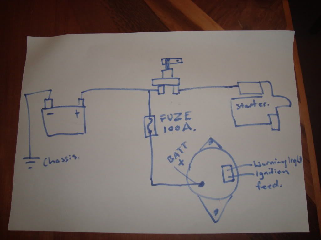
I've discovered what I think is the solution to all of these problems, firstly wiring the switch as follows from a Diagram posted on Skylines Australia (http://www.skylinesaustralia.com/forums/topic/324683-wiring-up-a-cams-approved-batt-isolator/):

A concern (and the reason for putting the alternator charge wire to the "always on" side of the switch) is that when you don't have a battery in place, load changes on the alternator by switching off high current devices such as lights/ignition etc can damage the alternator; in a normal car this extra momentary current increase from the alternator is absorbed by the battery, which acts as a huge capacitor. In the diagram above, the solution is that engine gets cut due to ignition and fuel pump being cut, and the battery is still there to take the current increase from that; while the engine/alternator spin down. The 100A fuse is there in case the cause for concern is a shorted alternator charge wire; this will cut that wire in that instance preventing further dramas. I will also have a single 5 or 10A wire running from the battery side of the switch to the KAM +ve on the ECU; this will ensure the ECU doesn't reset it's learning/adaption every time the car is switched off with the isolation switch.

I am still going to locate the switch on the transmission tunnel but have found a solution to the "externally accessible" part of the equation:

http://atspeedracing.co.uk/products/index.php?main_page=product_info&cPath=96&products_id=326&zenid=7c989739515573a56780d5a3188c5087
I will put this on a bracket at the switch (the switch has a provision for a lanyard/pull cable) and then run it to the fuel filler door, which will identify the presence of the switch with the standard blue triangle for ease of identification by marshals in case of a crisis.

Tuesday, December 11, 2012

Battery switch

I got my battery switch today, it is rated for 120A continuous or 500A for short periods (i.e. cranking). For only $18 they're a no brainer. Available from all Jaycar stockists.

Monday, December 10, 2012

No updates today

Hi all,

had a different project I spent some time on over the weekend, so didn't get any more work done on the E21. Plan to finish at least the driver's seat mount some time in the next few days though; and have cleared the pit side of the shed so I can get underneath to remove the engine/gearbox. This will mean I can finish welding the firewall and will be able to look at getting the good motor out of the Falcon and installed.

-C

Tuesday, December 4, 2012

Seat mounts

So the ECU wiring is in, and should hopefully work. I won't know for certain if it functions correctly until I actually get a motor (with manifolds etc intact) in to the car. The existing unit in the car is partially disassembled and was only fitted for sizing and mount building purposes.


In yet another tangent from the task immediately at hand, we started to work on a few other parts of the car needing attention. Firstly we are making seat mounts. I initially removed the existing rails from the seat and sat it directly on the floor, as far back as it could go (against the rear seat shelf) - this allowed about 10cm clearance between the top of my helmet and the lower-most part of the sunroof assembly, but did not allow me to see the bonnet. I could drive like this but it may prove difficult to see the track. I tried with around 30cm of books on top of the seat and this still allowed a decent amount of headroom but I could then see the front edge of the bonnet and the ground about 5m in front of the car, perfect.


I am going to use two bars as pictured above for the seat mounts; one can be RHS but because of the shape of the floor, the front mount needs to be angle iron welded in. I will then fit some angle iron to the seats themselves so that it sits on top of these bars - the angle will be bolted to the seats, and then the seats and this angle will sit in place and be bolted at each side of the seat, to allow the seat to be easily removed. I was initially going to bolt from under the floor but if that leaves exposed bolt heads there's a risk of them grinding or being snapped off if the car bottoms out. I still may use these rails as the mounts and cut an access hole in the underside of the floor to access the bolt heads, this should protect them enough to be OK to use this way.


While I started making the seat mounts, Fletcher came around and cut up an old table for some scrap RHS, which Michael H proceeded to turn into the battery box you see above. To help isolate the battery and the fuel, the battery will be run inside the car. I still have to look into sealing and ventilating it to somewhere outside the cabin - I believe I should be able to vent it to one of the C pillars as they have ventilation ducts there standard.


As it sits at the moment, I don't have any angle to make up the front "bar" mount, and I have to finish welding in the RHS bar as well. Once the driver's seat is mounted, we will be able to begin sorting out pedals (we need to use a falcon pedalbox, as the clutch is cable operated, also the BMW accelerator assembly was attached to part of the rusted floor that has since been removed. The brake pedal from the falcon should just require a hole drilled to accept the push rod from the BMW assembly to function.