Friday, December 14, 2012

Isolator switch bracket

Spent just over an hour last night making up the mount for the battery isolation switch last night from an offcut of aluminium chequerplate. The photo below doesn't show but the far side has about 3" going downwards; it's only sitting in the trans hole for the photo and will be mounted in about the same spot but on the interior side of the trans tunnel in approximately the location pictured.


The good news is, it looks like a factory Falcon starter motor wire will reach from this location to the starter motor without any further modification.

The reason I say "further" modification, is that I had to enlarge the holes to clear the stud for the isolation switch. Anyone planning on doing this, don't forget to make sure you have connectors that will fit on your existing cables, or buy some that will. Drilling/filing ring terminals is not particularly fun stuff!

Thursday, December 13, 2012

Battery "Isolation" Wiring


Went to mount my isolation switch last night and ran into a few queries that I couldn't find any quick or easy answers to; relating to where the switch is accessible from.

ANDRA (drag racing) says if the car runs quicker than 12s (1/4 mile) or 7.7s (1/8th mile) then it needs an externally accessible kill switch.

My original plan was to fit the switch in the cabin, within reach of the driver (and for Rally, within reach of the co-driver also) - the obvious location for this is the trans tunnel as with the battery located per pictures in previous posts (middle of back seat area) this is right in-line with where the battery wiring needs to run.

Rally Australia documents via CAMS state that while most Rally cars already run isolation switches, there is not actually a standard or a requirement relating to these; so that's safe for now, however one would assume that once standardised (or IF) that these switches will also need to be accessible by a marshal should the driver be incapacitated due to an accident.

I haven't yet been able to find info in CAMS but some posts on forums indicate that V8SC and other racing require this to be fitted to the base of the A-pillar. Given my seating position, this isn't a great idea as I can't REACH the A pillar with the seat mounted low and central as intended.

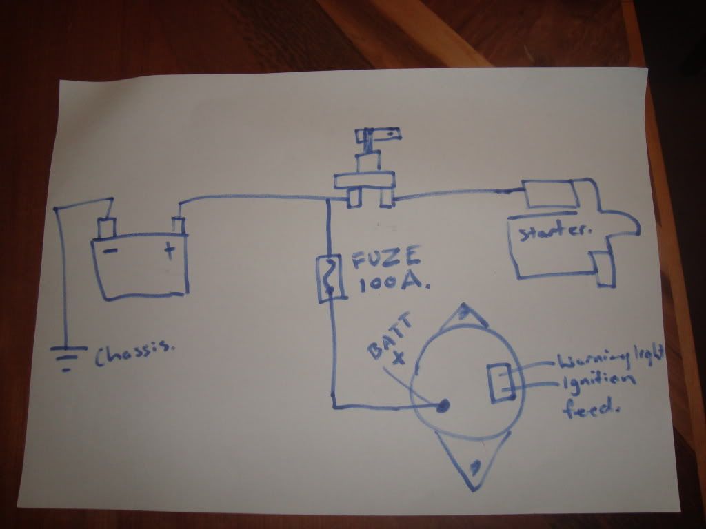
I've discovered what I think is the solution to all of these problems, firstly wiring the switch as follows from a Diagram posted on Skylines Australia (http://www.skylinesaustralia.com/forums/topic/324683-wiring-up-a-cams-approved-batt-isolator/):

A concern (and the reason for putting the alternator charge wire to the "always on" side of the switch) is that when you don't have a battery in place, load changes on the alternator by switching off high current devices such as lights/ignition etc can damage the alternator; in a normal car this extra momentary current increase from the alternator is absorbed by the battery, which acts as a huge capacitor. In the diagram above, the solution is that engine gets cut due to ignition and fuel pump being cut, and the battery is still there to take the current increase from that; while the engine/alternator spin down. The 100A fuse is there in case the cause for concern is a shorted alternator charge wire; this will cut that wire in that instance preventing further dramas. I will also have a single 5 or 10A wire running from the battery side of the switch to the KAM +ve on the ECU; this will ensure the ECU doesn't reset it's learning/adaption every time the car is switched off with the isolation switch.

I am still going to locate the switch on the transmission tunnel but have found a solution to the "externally accessible" part of the equation:

http://atspeedracing.co.uk/products/index.php?main_page=product_info&cPath=96&products_id=326&zenid=7c989739515573a56780d5a3188c5087
I will put this on a bracket at the switch (the switch has a provision for a lanyard/pull cable) and then run it to the fuel filler door, which will identify the presence of the switch with the standard blue triangle for ease of identification by marshals in case of a crisis.

Tuesday, December 11, 2012

Battery switch

I got my battery switch today, it is rated for 120A continuous or 500A for short periods (i.e. cranking). For only $18 they're a no brainer. Available from all Jaycar stockists.

Monday, December 10, 2012

No updates today

Hi all,

had a different project I spent some time on over the weekend, so didn't get any more work done on the E21. Plan to finish at least the driver's seat mount some time in the next few days though; and have cleared the pit side of the shed so I can get underneath to remove the engine/gearbox. This will mean I can finish welding the firewall and will be able to look at getting the good motor out of the Falcon and installed.

-C

Tuesday, December 4, 2012

Seat mounts

So the ECU wiring is in, and should hopefully work. I won't know for certain if it functions correctly until I actually get a motor (with manifolds etc intact) in to the car. The existing unit in the car is partially disassembled and was only fitted for sizing and mount building purposes.


In yet another tangent from the task immediately at hand, we started to work on a few other parts of the car needing attention. Firstly we are making seat mounts. I initially removed the existing rails from the seat and sat it directly on the floor, as far back as it could go (against the rear seat shelf) - this allowed about 10cm clearance between the top of my helmet and the lower-most part of the sunroof assembly, but did not allow me to see the bonnet. I could drive like this but it may prove difficult to see the track. I tried with around 30cm of books on top of the seat and this still allowed a decent amount of headroom but I could then see the front edge of the bonnet and the ground about 5m in front of the car, perfect.


I am going to use two bars as pictured above for the seat mounts; one can be RHS but because of the shape of the floor, the front mount needs to be angle iron welded in. I will then fit some angle iron to the seats themselves so that it sits on top of these bars - the angle will be bolted to the seats, and then the seats and this angle will sit in place and be bolted at each side of the seat, to allow the seat to be easily removed. I was initially going to bolt from under the floor but if that leaves exposed bolt heads there's a risk of them grinding or being snapped off if the car bottoms out. I still may use these rails as the mounts and cut an access hole in the underside of the floor to access the bolt heads, this should protect them enough to be OK to use this way.


While I started making the seat mounts, Fletcher came around and cut up an old table for some scrap RHS, which Michael H proceeded to turn into the battery box you see above. To help isolate the battery and the fuel, the battery will be run inside the car. I still have to look into sealing and ventilating it to somewhere outside the cabin - I believe I should be able to vent it to one of the C pillars as they have ventilation ducts there standard.


As it sits at the moment, I don't have any angle to make up the front "bar" mount, and I have to finish welding in the RHS bar as well. Once the driver's seat is mounted, we will be able to begin sorting out pedals (we need to use a falcon pedalbox, as the clutch is cable operated, also the BMW accelerator assembly was attached to part of the rusted floor that has since been removed. The brake pedal from the falcon should just require a hole drilled to accept the push rod from the BMW assembly to function.

Sunday, December 2, 2012

Odd jobs

Got a bit bored with wiring so have done a little bit of a few other tasks.

Partially re-made the front radiator support area (pictures when it's done) so the light surrounds can be mounted properly.

Also made some headway into cutting out the boot floor to allow a falcon fuel tank to fit, I am going to avoid using a fuel cell unless completely necessary in the aim of keeping this as low-budget as possible.

I also gave the car a quick wash and machine polish; it came up pretty well considering it hasn't had more than a single pressure wash in the last two years or more.


There are some other things I'd like to do too (like cutting the springs) but I'm missing a few assorted bits and pieces to make them happen (i.e. cutting wheels for the grinder) - I'll have to grab those sorts of things over the next few weeks so I can cross some more of these tasks off the list.

Tuesday, November 27, 2012

Wires, wires and more wires!

Just spent three hours untaping a whole Falcon worth of looms. We won't need anywhere near the whole lot, so this will make the process of removing the unneeded wires much easier.

These photos show a LOT of wires, but it doesn't even come close to conveying just how many are here... just wow.


Progress Update

So, I have made some decent progress on the wiring today. Got the parker and low beam switch worked out, wired up and tested working all ok. Got the reverse light wired to the falcon gearbox and tested working all ok. Got the brake light switch wired up and working with the BMW pedalbox.

Took a quick snap of my daughter Scarlett putting the wiring through its paces - she loves playing with buttons and switches etc :)


Next job was to get the control panel wired before I start doing the motor loom. I've had the panel in the car for some time (I believe there are more photos down below of this), but nothing had been connected. It's now wired and back in the car, so I can start setting up relays etc for the various functions I have placed on this board.

Sunday, November 25, 2012

Wiring

Finally made a start to the wiring on the car over the last few days.

Since I started, I eventually tracked down a PDF wiring manual http://www.jtresto.com/e21/ETM_1979.pdf, but initially I went through with a battery charger and connected individual pins to determine which wires for the rear lights were which. I was a bit hasty removing the original wiring from the car so this was cut off at the base of the back seat. Once I'd determined which wires were for what, I extended them (with the original loom, which I still have, as I figured I'd need the connectors - thank god I did that - more on that later!). I am going to run the relays for everything in the car at the passenger footwell. I'll be putting a bar to stop passengers from being able to kick anything loose. The Battery will be in the boot and the master switch will be in the centre console near the hand brake and shift lever so either the driver or passenger can turn it off.

I dug out the engine bay loom and untaped it, then seperated out everything except the two headlight and indicator loom wires, shortened the ground wires and put terminals on them, and then extended this wiring and ran it also into the footwell.

I joined the front and rear indicators, and parker wiring together, and tested that I had all the things I wanted (I don't think I need a horn, I don't have a horn switch anyway) --> Headlights, Parkers, Indicators, High Beam, Reverse Lamps. I also ran the wire to the footwell for the rear demister. I don't know if I'll need it but it's easier to run the wiring now than to leave it until later and have to find/run it.

Then (and this is where keeping the connectors comes in) I tried to work out how the combination switch (High/Low and Left/Right indicators) works - turns out there is a (very proprietary) 12 pin plug (approx) and inside this plug these switches have both their pins wired; so you need to find BOTH matching pins to be able to use the switch. It's probably not a massive surprise for those of you who have done this sort of thing before, but it sure makes using a multimeter to work out which wires are used very time consuming - in the end I gave up and tracked down the wiring diagram mentioned above.

I've also cut back the loom for the hazard switch, and will be connecting that as well; it will get it's power (fused) from in front of the master switch, so the hazards can still be run in any incident where the rest of the power has to be cut off. The fuse should protect it from any other dramas though.

I taped an E-series flasher unit to a couple of relays, and have wired up the relays for the indicators/hazards, now I have to wire the indicator light into the hazard switch and connect it and the combo switch up for a test run. Once that's done, lights are practically done (N.B. I still have to work out the dash lamp wiring, but I'll treat that as a different job I think!)

Thursday, November 8, 2012

No news, so I'll post some photos instead!

Bonnet and front back on; almost forgot what it looked like!

Worked out that my sunroof actually opens! All along, I'd only thought it was a tilt roof as it just clicked like a ratchet when trying to turn the handle the other way (although it went too far past closed and seemed odd that there were rails for it to open right up). Managed to give it a bit of manual persuasion (pusing down and back on the top of the roof while winding the handle) and it opened. Once it got past the initial difficulty, it opened very easily and freely. It's still a bit stiff at the extreme point of closing or opening but I think that's just the interior trim catching on the frame, so I'll have a go removing that and then see if it's any better. Since the car will have limited ventilation when it's done, being able to open the sunroof will be a massive benefit for airflow through the car.

Had a stuck front wheel bearing or brake rotor corroded, to the point my normal method of moving the car (ride-on lawn mower) wouldn't move it, and you couldn't turn the wheel by hand. Hooked up one of the other cars in the yard (Ford Fairmont, also powered by a 4L I6) and it started moving no worries. Seems to roll fairly freely now so I'm going to assume it was just corrosion on the brake rotor from a bit of water.

Finally, here's a quick video of my (now retired) EB with the motor that currently seems destined to end up in the E21:

Sunday, September 9, 2012

Radiator

So, I got a bit carried away making room for the radiator. I am using a standard Falcon Radiator because it's perfectly suited to the motor, and because it's the same width as the engine bay :)
As you can see, it fits!
Still some fine tuning to do here to ensure the hose won't get rubbed through by metal, should only be minor work required though.
Will have to make some covers for this light - I prefer the twin-light look, so it'll be a bit like the Jagermeister Group 5 car :)
Routing this hose to the reservoir could prove to be interesting, the headlight bracket is going to be a bit of work!