Went to mount my isolation switch last night and ran into a few queries that I couldn't find any quick or easy answers to; relating to where the switch is accessible from.
ANDRA (drag racing) says if the car runs quicker than 12s (1/4 mile) or 7.7s (1/8th mile) then it needs an externally accessible kill switch.
My original plan was to fit the switch in the cabin, within reach of the driver (and for Rally, within reach of the co-driver also) - the obvious location for this is the trans tunnel as with the battery located per pictures in previous posts (middle of back seat area) this is right in-line with where the battery wiring needs to run.
Rally Australia documents via CAMS state that while most Rally cars already run isolation switches, there is not actually a standard or a requirement relating to these; so that's safe for now, however one would assume that once standardised (or IF) that these switches will also need to be accessible by a marshal should the driver be incapacitated due to an accident.
I haven't yet been able to find info in CAMS but some posts on forums indicate that V8SC and other racing require this to be fitted to the base of the A-pillar. Given my seating position, this isn't a great idea as I can't REACH the A pillar with the seat mounted low and central as intended.
I've discovered what I think is the solution to all of these problems, firstly wiring the switch as follows from a Diagram posted on Skylines Australia (http://www.skylinesaustralia.com/forums/topic/324683-wiring-up-a-cams-approved-batt-isolator/):
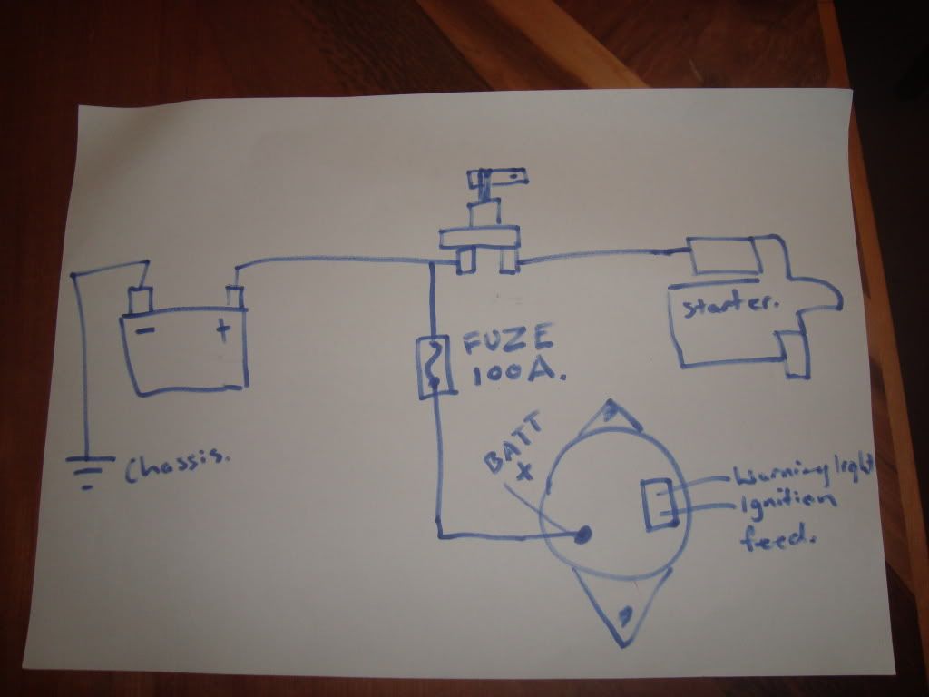
A concern (and the reason for putting the alternator charge wire to the "always on" side of the switch) is that when you don't have a battery in place, load changes on the alternator by switching off high current devices such as lights/ignition etc can damage the alternator; in a normal car this extra momentary current increase from the alternator is absorbed by the battery, which acts as a huge capacitor. In the diagram above, the solution is that engine gets cut due to ignition and fuel pump being cut, and the battery is still there to take the current increase from that; while the engine/alternator spin down. The 100A fuse is there in case the cause for concern is a shorted alternator charge wire; this will cut that wire in that instance preventing further dramas. I will also have a single 5 or 10A wire running from the battery side of the switch to the KAM +ve on the ECU; this will ensure the ECU doesn't reset it's learning/adaption every time the car is switched off with the isolation switch.
I am still going to locate the switch on the transmission tunnel but have found a solution to the "externally accessible" part of the equation:
http://atspeedracing.co.uk/products/index.php?main_page=product_info&cPath=96&products_id=326&zenid=7c989739515573a56780d5a3188c5087

Found two options in Australia (cost will end up about the same)
ReplyDeletehttp://www.autosportdirect.com.au/itemdetailspage/15465
http://www.autosportdirect.com.au/itemdetailspage/14728